An inverter
In the second post in the Concepts series we will discuss another simple logic gate, an inverter.
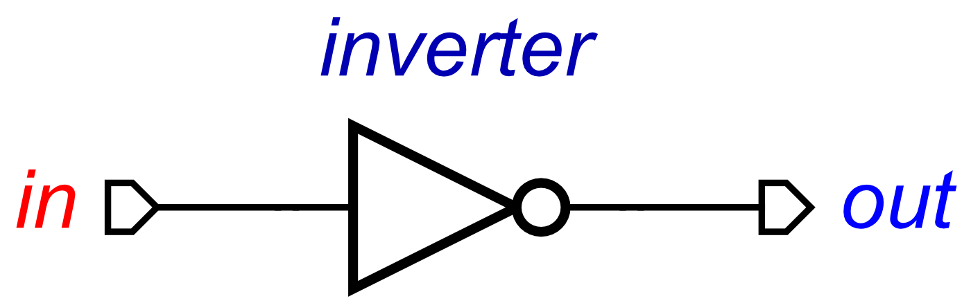
An inverter takes an input signal, and outputs a signal in the opposite, or inverted, state as the input signal, the output is simply the opposite of the input. For example, if the input signal changes from 0 to 1, the output will eventually change from 1 to 0. Similar to with the buffer, and the same with all gates, we say the output changes ‘eventually’ because the output changes after some unknown delay.
So how do we design an inverter using concepts? We need to describe what causes the output to transition, in terms of when the input transitions. This can be described as:
inverter(in, out) = in+ ⇝ out- ⋄ in- ⇝ out+
This is very similar to the buffer concept, but with some subtle differences. This concept implies that in+ causes out-. This is composed with in- causing out+. Therefore, this concept suggest that when the input transitions one way, the output will eventually transition in the opposite direction, for example, when in+ occurs, out- will eventually occur after, providing in stays high.
As with the previous post, we need to produce an STG from the inverter concept, which we can simulate, verify and test. To do this, we pass this into the conversion algorithm, which starts as follows:
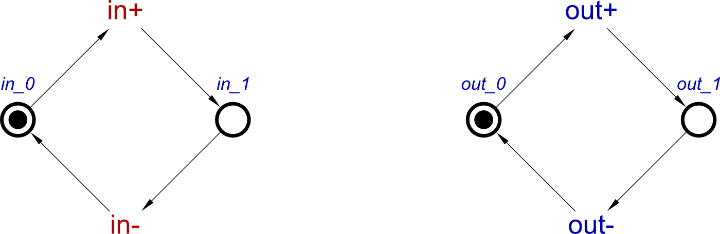
As with the buffer, it starts off by placing cycles for each individual signal. This keeps the property of consistency in the STG, as discussed in Concepts I.

Next, the first causality of the inverter concept is applied to these cycles. This is in+ ⇝ out-. This connects the place after in+, labelled as in_1, with the signal transition of out-, using a read-arc. This is so that for out- to occur, in must have already transitioned high, which is displayed by in_1 possessing a token. The read-arc stops out- from consuming the token in in_1 which would block in- from happening, but allows out- to occur.
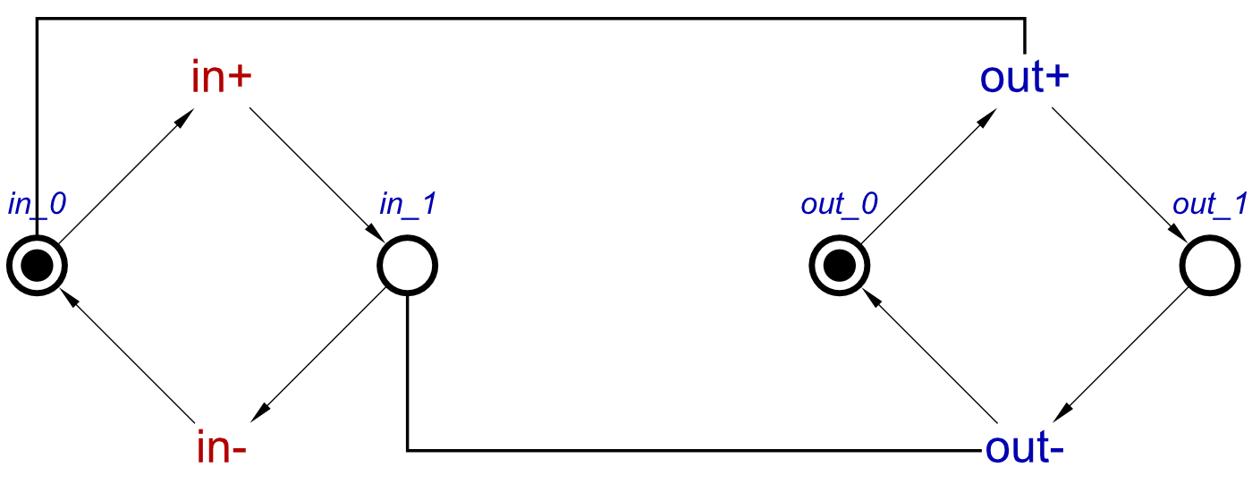
Finally, another read arc is used which represents the concept of in- ⇝ out+, connecting in_0 place with the out+ transition. This conversion of a concept to an STG is now complete, and this correctly represents the operation of an inverter.
Note, as with the buffer STG, that in the above STGs we assume that all signals are initialised to 0. In this case, it means that the output can initially transition high and will do eventually, due to the fact that in input is initially 0.
In a later blog post we will see how to use concepts to specify initial states of all signals in a compositional manner.
More reuse
We have now defined both an inverter and a buffer in these first two posts. So lets use these together to show some reuse, and how these can be used together.
For this example, lets use a buffer and inverter loop. It doesn’t necessarily have any real-world applications as these logic gates, but it’s a perfect example to show how concepts can be composed, and produces some interesting results.
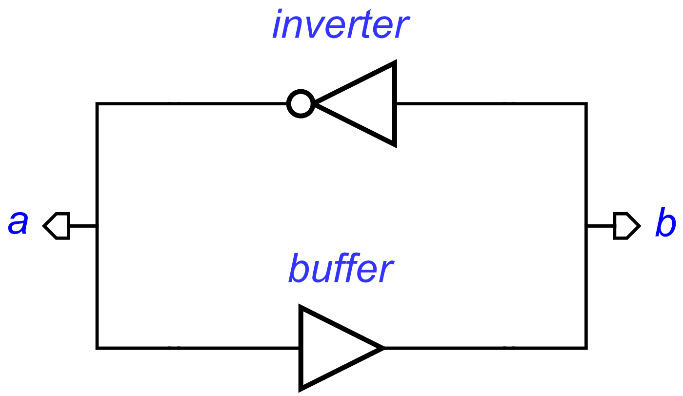
The signals shown in this diagram are simply used for viewing the outputs from the inverter and the buffer, but can be used as part of the concepts.
This circuit can be produced from the following concept:
bufferAndInverter = buffer(a,b) ⋄ inverter(b,a)
In this circuit, a is an input to the buffer, but the output from the inverter, and these are connected. b is another signal connecting the output of the buffer to the input of the inverter.
As with the doubleBuffer example from the previous post, we could have described this using signal-level concepts, which would be a longer description that that of the one above. Since we have defined both an inverter and a buffer, we can simply reuse this definition in order to save time on describing concepts. The bufferAndInverter STG will be, assuming all signals are initially 0, as follows:
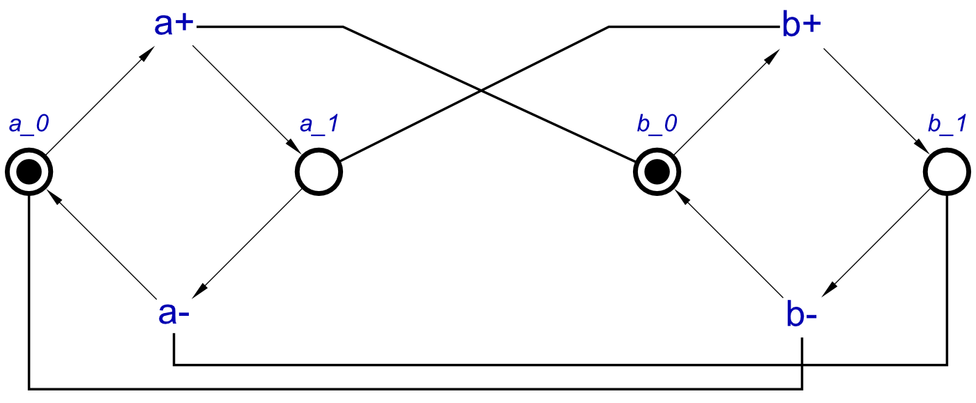
By following pairs of arcs, it is possible to see which are a cause of the buffer, and which are a cause of the inverter. This STG can now be simulated, and does in fact act as expected from the circuit above. When a+ occurs, b+ is enabled, and after it transitions, this will cause a- to be enabled. When a- has occurred, b- can then occur, after which a+ is enabled, and this completes the circuit.
This STG can be resynthesized, and the result is rather interesting:
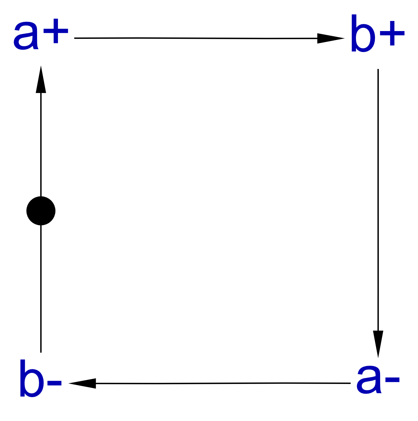
The resulting STG is in-fact the STG for a handshake protocol. This means that what we have defined above, bufferAndInverter, is actually a handshake, described using a buffer and an inverter. Therefore, let’s drop the current name, and re-define it using some parameters, so that any pair of signals can be handshaked.
handshake(a,b) = buffer(a,b) ⋄ inverter(b,a)
Handshakes are very useful for asynchronous systems, and having a concept defined for use at any time can make the design process much easier and quicker.
Finally
In this post, we have discussed how to describe a second logic gate, an inverter. We have described this in terms of concepts, and shown the conversion to produce an STG. We have also shown how a buffer and an inverter can be used in conjunction with one-another to produce a circuit, now that both have been pre-defined.
The next post, Concepts III: Initial States will use buffers and inverters as examples of how initial states can be defined using concepts, or in the case that initial states are not defined, how the conversion algorithm will apply options for initial states, so an STG produced can still be used for simulation.