Initial States
Now we have introduced a couple of simple gates, a buffer and an inverter, we should now discuss an important part of Signal Transition Graphs, and their implementation using Concepts. These are initial states.
Initial states are used in Signal Transition Graphs to show what state a signal is in, high or low, when the system being designed starts. This is important as STGs require initial states for simulation, verification and synthesis.
In the previous posts, we have assumed that all signals involved in the STGs are initially set to 0, and this has been indicated by placing a token in the places which are before each signals + transition (as above), but this assumption cannot be applied to every STG.
Example – A Handshake
So now let’s use a previous example, a Handshake, and discuss what we can do to ensure there are initial states in an STG produced using concepts.
The concept used to describe a handshake is as follows:
handshake(a,b) = buffer(a,b) ⋄ inverter(b,a)
This concept captures the interactions of signals a and b, using previously defined buffer and inverter concepts, but this does not explain the state of these signals when the handshake starts.
Initial state concepts can be defined similarly to other concepts, and thus can be composed with other concepts as normal. For this example, let’s say the two signals involved in handshake are both initially 0.
initialState = initialise(a,0) ⋄ initialise(b,0)
There is some syntax to discuss here:
initialise(a,0) – This is used to express an initial state. The state of the signal, a, will be initially set to 0.
The concept, initialState, implies that the initial state of signals a and b will be 0, so the first transition of each can be +, from low to high.
Now we can include this concept with the handshake concept:
system = handshake(a,b) ⋄ initialState
Passing this concept into the algorithm will produce the same STG as in the previous post:
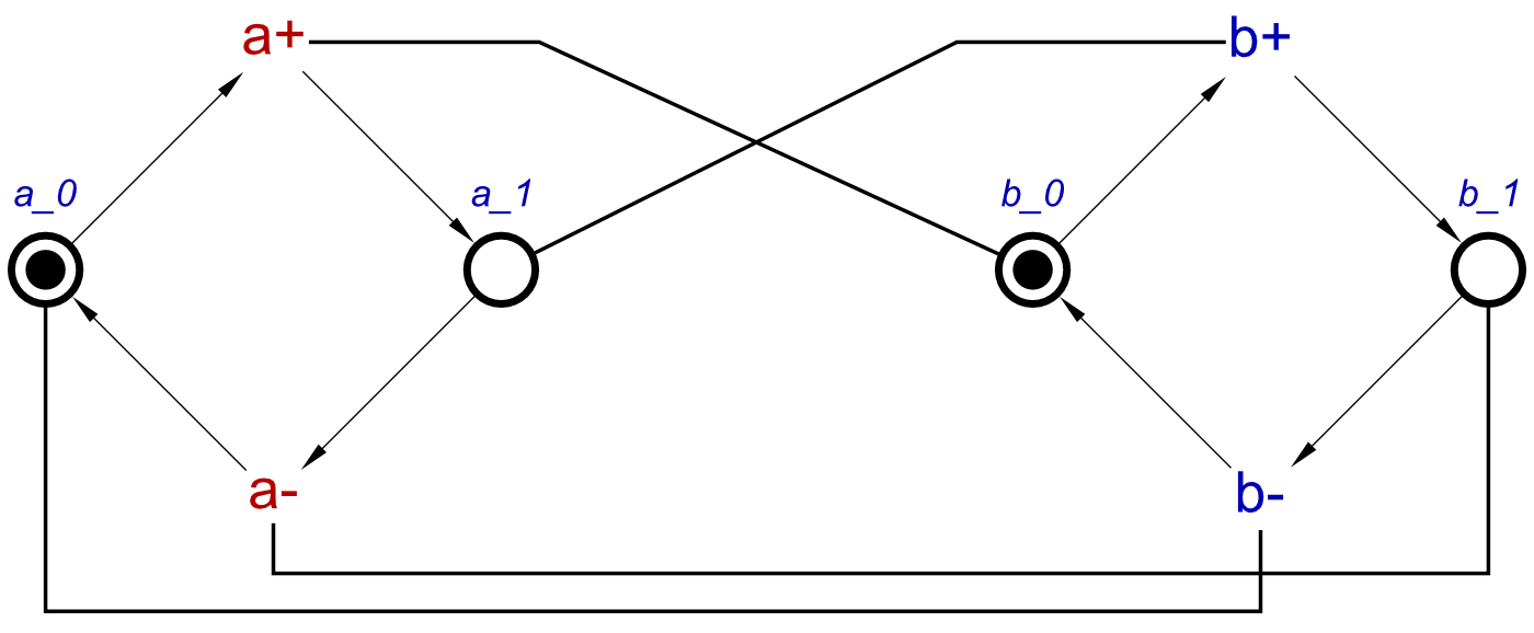
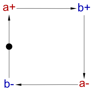
And this can be resynthesized to produce the same handshake STG:
However, what if the initial states are not both 0? For this, let’s redefine the initial state concept and compose this with a handshake concept:
initialState = initial(a,0) ⋄ initial(b,1)
system = handshake(a,b) ⋄ initialState
Now, a should initially be 0, and b should initialy be 1. The STG produced from these concepts is:
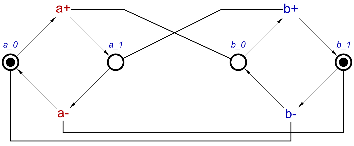 This is the same as the previous version, but the tokens have shifted. After resynthesis, the STG is as follows:
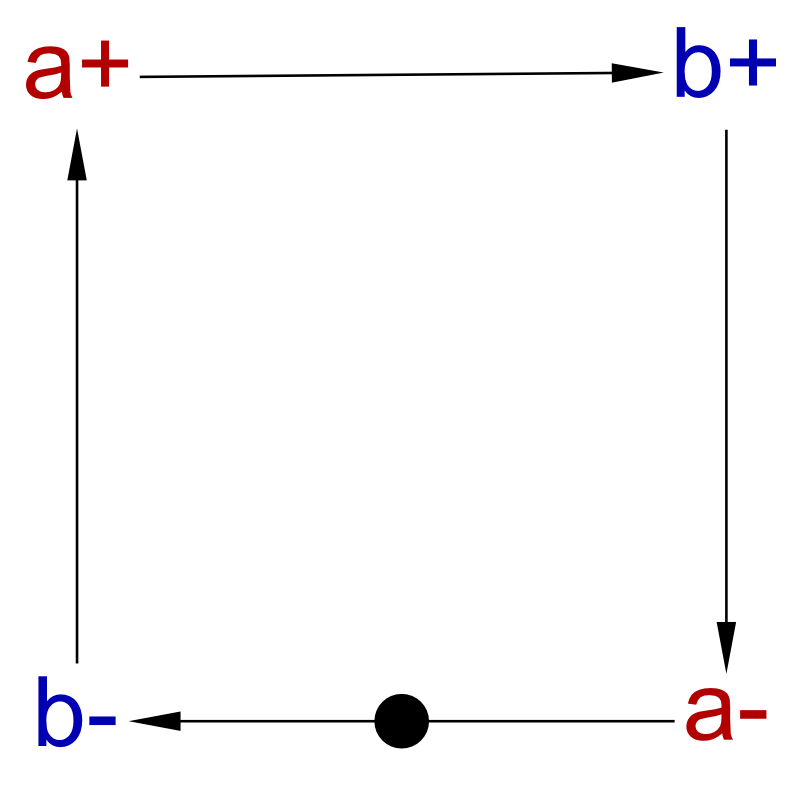 Again, very similar to the previous post-resynthesis STG. But in this case, we can see that b- is the first transition, instead of a+.
No initial state concepts
So, what if a set of concepts doesn’t contain any initial state concepts. In this case, the STG produced may still be a correct implementation of the system, but a user may wish to do some testing with options for initial states open.
When this occurs, the algorithm has the option of adding some extra transitions to allow a user some options. So, for example, let’s define a handshake, but no initial states:
system = handshake(a,b)
In this case, we make no assumptions of initial states, but how does this affect the STG produced?
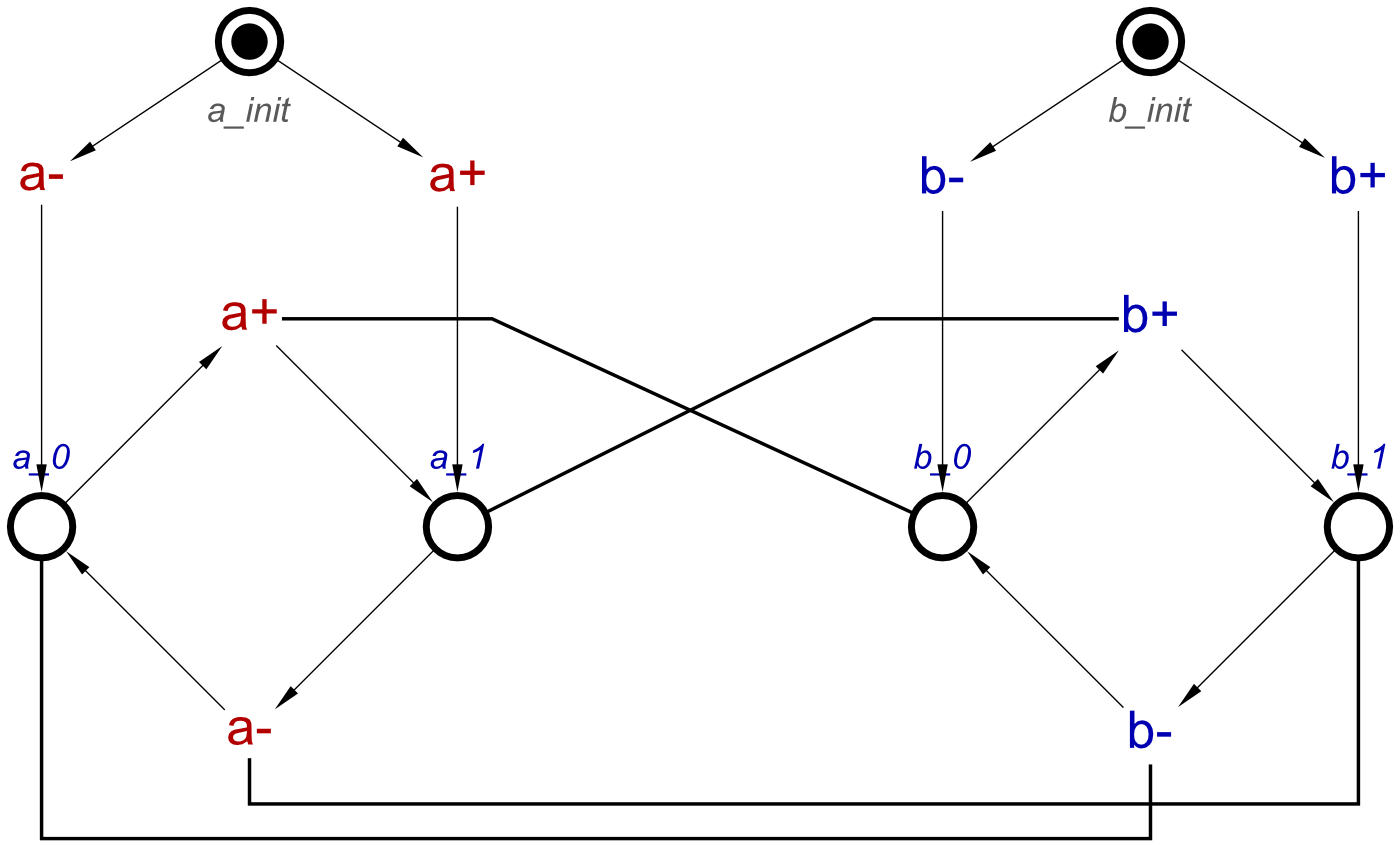
The STG produced is very similar to the previous STG, the concepts used to describe which features initial states. In this case however, the places a_0, a_1, b_0 and b_1 are all free from tokens. In order to select an initial state, the algorithm adds in an extra place and two extra transitions per signal, in order to allow a choice of each signal’s initial state.
Using this example, when a user starts the simulation, the first transitions to be enabled will be the transitions either high or low from the initial state selections, allowing the user to select a- to set this signal to 0 initially, or a+ to set it to 1 initially, and this is the same as with signal b.
After this choice is made, the initial state selection will no longer be usable until the simulation is started again. The user can test how the system runs using these initial states, and then restart to test another combination of initial states. After the initial states have been selected, the user can either change this STG, removing the initial state selections and adding tokens into the correct place, or they can add the initial states to the list of concepts, and re-compose these for a new STG.
DISCLAIMER – An STG featuring initial state selection is not a correct STG, it violates properties of STGs which are necessary in order to be used with tools which perform useful functions like synthesis, for example. Currently, this method of testing for initial states should be used only for simulation, to test how differing initial states can affect a system. Any future developments are made on how to include a choice of initial state in a correct STG, a follow-up post will be made.
Finally
In this and the previous two posts, we have covered the basics of concepts, and the design process of various simple gates. Now we can move onto discussing some more complicated designs, and how we can use pre-existing concepts, and define new ones.
The next blog post will be Concepts IV: A C-element. This will be the first in a set of posts describing some standard logic gates, and from this we will work up to some more complex examples, using some of the previously described gates.