Feb 222017
 

It’s so long since my last post – sorry! Development of the sensor software stalled after linux changed the way it recognises devices and introduced so many bugs and difficulties I was left grinding my teeth in exasperation.

Still playing with the Raspberry Pi, however, but for now the focus is on communication over WiFi, with the aim of being able to control a car or other vehicle using a web interface. Ultimately I want to get this working with MQTT – essentially an IoT solution – but initially this will use a web server and HTTP.

A computer-controlled car – and here I’ll assume the computer is a WiFi-enabled Raspberry Pi running linux – needs to interact with the human (or other remote) controller, and needs to look after itself, i.e., check the sensors for obstacles, update the current drive settings, adjust the steering, etc. In other words, it needs to multitask. The best way to do this is via threads. It also makes sense to have an event loop.

Given all these requirements, I have created a project that implements the basic logic: wifi-py-rpi-car-controller

  • Written in Python and using threading and Queue for event management, and web.py for the web server; also NumPy, although that’s not a hard requirement at this stage.
  • Currently the web interface is written as a single non-templated HTML document with a 2D ‘slider’ written with SVG, although I’ll probably fix this to allow separate handling of linked CSS and Javascript files. A query/command mechanism is provided for passing instructions to the car controller (via the server) and receiving data from it.
May 042014
 

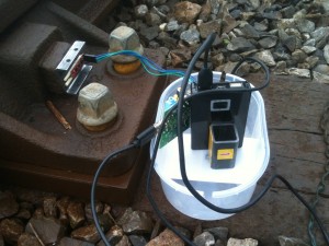
To take measurements on railway track (possibly miles from civilisation), it is useful to have a system that doesn’t require mains power or display, keyboard, etc. In this case I used:

  • 5000mAh Li-Ion Rechargeable Power Bank; supplied by RS Online (775-7508)
  • Belkin Cable Transfer Windows 8; supplied by RS Online (779-8827)

Raspberry Pi Type A with Sparkfun Sensor Stick used to monitor railway track

Raspberry Pi Type A and Sparkfun Sensor Stick used to monitor railway track


Power Source

The Power Bank is a rechargeable battery that is powered through a USB connection, and that supplies power to two USB-powered devices. In this case it is used to power only the Raspberry Pi Type A, and was used extensively over a 24-hour period without need for recharge.

Ethernet Communication between Raspberry Pi and Laptop

The Transfer Cable masquerades as an ethernet connection on Linux and was used to connect the Raspberry Pi with a Dell Laptop (with Debian Wheezy 7.4.0 newly installed). Of course, there are other ways to establish a link between the the Raspberry Pi and the outside world, and I plan to get it working via WiFi and radio in the near future, but the hard-wired connection has other potential applications. Also, it can be unplugged and then plugged in again, so is probably the lowest-power option.

To get the Raspberry Pi to recognise and configure the USB connection, add the following settings for usb0 in /etc/network/interfaces:

allow-hotplug usb0
iface usb0 inet static
    address 192.168.99.2
    netmask 255.255.255.0
    gateway 192.168.99.1

Update: Actually, the gateway setting isn’t necessary – I have tested the Belkin cable on a Raspberry Pi Type B*1 without the gateway setting and it works fine. The gateway setting is required if you want to share the laptop’s internet connection – in which case, you will also need to configure iptables on the laptop*2.

*1 I read somewhere that the Belkin cable doesn’t work with the Type B, but it seems to work fine for me.
*2 I used ufw for this, which is easy enough to use, but where things do get complicated is with nameserver configuration on the Raspberry Pi.

Something similar needs to be done on the laptop:

allow-hotplug usb0
iface usb0 inet static
    address 192.168.99.1
    netmask 255.255.255.0

Results

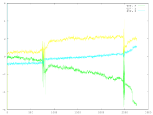
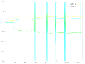
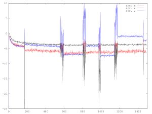
The graphs below are accelerometer and gyro measurements averaged over a period of one second. The sensors were collecting data continuously and most of the time there was no activity. The passing trains appear as a compressed burst of movement, against which long-term changes are apparent.

Gyro on rail web: Deltics and Class 37

Gyro on rail web: Deltics and Class 37

Accelerometer on rail web: Deltics and Class 37

Accelerometer on rail web: Deltics and Class 37

Above: The Deltic arrived at Barrow Hill preceded by a Class 37, and later they left with a second Deltic coupled behind.

Gyro on rail web: 0-3-0, Class 40 and Class 45

Gyro on rail web: 0-3-0, Class 40 and Class 45

Accelerometer on rail web: 0-3-0, Class 40 and Class 45

Accelerometer on rail web: 0-3-0, Class 40 and Class 45

Above: The 0-3-0 passed first, collected the Class 40 and Class 45 for a total of four passes, then uncoupled and returned.

Apr 162014
 

The hardware I’m using here is a Raspberry Pi Type A, described in detail here. My previous post (Part 1: Modules and Packages) configured the Raspberry Pi to use the I2C connection. The aim in this post is to connect to a SparkFun 9DOF Sensor Stick (SEN-10724) which has a 3-axis accelerometer (ADXL345), a 3-axis gyro (ITG-3200) and a 3-axis compass / magnetometer (HMC5883L) all sharing an I2C interface.

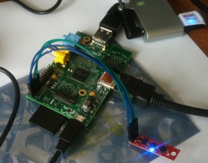
Raspberry Pi Type A connected via I2C with a SparkFun 9DOF Sensor Stick (SEN-10724)

Raspberry Pi Type A connected via I2C with a SparkFun 9DOF Sensor Stick (SEN-10724)


There are three separate devices on the sensor stick all hooked up to the same I2C bus. You can see the addresses listed below. The HMC5883L compass / magnetometer uses address 1e. The ADXL345 accelerometer uses address 53. The ITG-3200 gyroscope uses address 68. (The ‘UU’ at address 3b indicates an address reserved by the kernel, but I don’t know for what.)

~ $ sudo i2cdetect -y 1
     0  1  2  3  4  5  6  7  8  9  a  b  c  d  e  f
00:          -- -- -- -- -- -- -- -- -- -- -- -- -- 
10: -- -- -- -- -- -- -- -- -- -- -- -- -- -- 1e -- 
20: -- -- -- -- -- -- -- -- -- -- -- -- -- -- -- -- 
30: -- -- -- -- -- -- -- -- -- -- -- UU -- -- -- -- 
40: -- -- -- -- -- -- -- -- -- -- -- -- -- -- -- -- 
50: -- -- -- 53 -- -- -- -- -- -- -- -- -- -- -- -- 
60: -- -- -- -- -- -- -- -- 68 -- -- -- -- -- -- -- 
70: -- -- -- -- -- -- -- --

2. Connecting to the Sensor Stick

I’m not the first to use this stick, and there is, for example, a project by Peter Bartz which uses the stick:
Attitude and Heading Reference System (AHRS). More useful, perhaps, is Rolfe Schmidt’s muCSense work with it here and here.

All three I2C devices have open source (MIT license) C++ device libraries available from I2Cdevlib:

These rely on the underlying Wire class written for the Arduino, however, so a Raspberry Pi implementation of the Wire class is necessary (and one or two other miscellaneous functions).

I am currently working on this – find the latest source here, and a discussion topic here.

Mar 232014
 

The hardware I’m using here is a Raspberry Pi Type A, described in detail here. The aim in this post is to connect to the I2C interface.

1. Configuring the Raspberry Pi to use I2C

First things first, set up the Raspberry Pi to use I2C. Here’s a good guide: Configuring Your Pi for I2C. (And another.)

1. Start by installing some extra packages (developer page here):

sudo apt-get install python-smbus
sudo apt-get install i2c-tools
sudo apt-get install libi2c-dev

2. Check the blacklist:

~ $ cat /etc/modprobe.d/raspi-blacklist.conf 
# blacklist spi and i2c by default (many users don't need them)

blacklist spi-bcm2708
blacklist i2c-bcm2708

and disable those two last lines (edit with nano):

~ $ cat /etc/modprobe.d/raspi-blacklist.conf 
# blacklist spi and i2c by default (many users don't need them)

#blacklist spi-bcm2708
#blacklist i2c-bcm2708

3. Check the list of modules:

~ $ cat /etc/modules
# /etc/modules: kernel modules to load at boot time.
#
# This file contains the names of kernel modules that should be loaded
# at boot time, one per line. Lines beginning with "#" are ignored.
# Parameters can be specified after the module name.

snd-bcm2835

and add two more modules to the list there:

~ $ cat /etc/modules
# /etc/modules: kernel modules to load at boot time.
#
# This file contains the names of kernel modules that should be loaded
# at boot time, one per line. Lines beginning with "#" are ignored.
# Parameters can be specified after the module name.

snd-bcm2835
i2c-dev 
i2c-bcm2708

4. (Optional) To allow non-administrator users to use I2C, you can use this handy trick (thanks here to Raspberry Pi I2C udev rules).

Create a file /etc/udev/rules.d/90-i2c.rules and add the line:

KERNEL=="i2c-[0-7]",MODE="0666"

5. (Optional) To adjust the clock speed of the I2C (the default is 100kHz but many I2C devices can operates at 400kHz), then here’s another handy trick (thanks here to Setting the Raspberry Pi I2C ports to operate at 400kHz). Create a file /etc/modprobe.d/i2c.conf and add the line:

options i2c_bcm2708 baudrate=400000

6. Reboot.

7. One final step if you skipped Step 4 and if you don’t want to use I2C as an administrator – give everyone read-write access to the devices:

~ $ sudo chmod o+rw /dev/i2c-*

It will be necessary to do this after every reboot.

2. Testing the I2C Connection

Linux has I2C support in the kernel (see kernel documentation for details of the interface), and here’s a nice tutorial explaining the simplest way to use it.

I’m going to cheat and use a test program – check_I2C.c by Vincenzo Villa:

// Rapsberry Pi: I2C in C - Versione 0.61 - Luglio 2013
// Copyright (c) 2013, Vincenzo Villa (http://www.vincenzov.net)
// Creative Commons | Attribuzione-Condividi allo stesso modo 3.0 Unported.
// Creative Commons | Attribution-Share Alike 3.0 Unported
// http://www.vincenzov.net/tutorial/elettronica-di-base/RaspberryPi/i2c-c.htm

// Compile:  gcc check_I2C.c -std=c99 -o check_I2C
// Run as user with R&W right on /dev/i2c-* (NOT ROOT!)
// vv@vvrpi ~ $ ./check_I2C 
// Check whether some i2c functionality are present

#include <stdint.h>
#include <unistd.h>
#include <stdio.h>
#include <stdlib.h>
#include <getopt.h>
#include <fcntl.h>
#include <sys/ioctl.h>
#include <linux/types.h>
#include <linux/i2c-dev.h>

#define I2C_ADDR 0x4B				// Device adress

#define LM92_TEMP 0                             // Temperature register (see data sheet)
#define LM92_RES 0.0625                         // Resolution (see data sheet)

static const char *device = "/dev/i2c-1";	// I2C bus

static void exit_on_error (const char *s)	// Exit and print error code
{ 	perror(s);
  	abort();
} 

int main(int argc, char *argv[])
{
	int fd;
	
	int32_t functionality;
	uint8_t  buffer[2];
        int16_t  data;
        double   temperature;
        
        printf("Rapsberry Pi: I2C in C - Versione 0.61 - Luglio 2013\n");
        printf("Copyright (c) 2013, Vincenzo Villa (http://www.vincenzov.net)\n");
        printf("Creative Commons | Attribuzione-Condividi allo stesso modo 3.0 Unported.\n");
        printf("Creative Commons | Attribution-Share Alike 3.0 Unported\n");
        printf("http://www.vincenzov.net/tutorial/elettronica-di-base/RaspberryPi/i2c-c.htm\n\n");                                       

       	// Open I2C device
       	if ((fd = open(device, O_RDWR)) < 0) exit_on_error ("Can't open I2C device");

        if (ioctl(fd, I2C_FUNCS, &functionality) < 0)  exit_on_error ("Can't use I2C_FUNCS ioctl");
        
        printf("Raw data from driver (I2C_FUNCS): 0x%.8X\n", functionality);        
        
        printf("\nI2C_FUNC_I2C ");
        if ( I2C_FUNC_I2C & functionality) printf("\t\t\t\tOK");      

        printf("\nI2C_FUNC_10BIT_ADDR ");
        if ( I2C_FUNC_10BIT_ADDR & functionality)  printf("\t\t\tOK");
                                                                                                        
        printf("\nI2C_FUNC_PROTOCOL_MANGLING ");                 
        if ( I2C_FUNC_PROTOCOL_MANGLING & functionality) printf("\tOK");                   

//        printf("\nI2C_FUNC_NOSTART ");
//        if ( I2C_FUNC_NOSTART & functionality) printf("\tOK");
                
        printf("\nI2C_FUNC_SMBUS_QUICK ");
        if ( I2C_FUNC_SMBUS_QUICK & functionality) printf("\t\t\tOK");
                
        printf("\nI2C_FUNC_SMBUS_READ_BYTE ");
        if ( I2C_FUNC_SMBUS_READ_BYTE & functionality) printf("\t\tOK");
                
        printf("\nI2C_FUNC_SMBUS_WRITE_BYTE ");
        if ( I2C_FUNC_SMBUS_WRITE_BYTE & functionality) printf("\t\tOK");
                                                               
        printf("\nI2C_FUNC_SMBUS_READ_BYTE_DATA ");
        if ( I2C_FUNC_SMBUS_READ_BYTE_DATA & functionality) printf("\t\tOK");
                
        printf("\nI2C_FUNC_SMBUS_WRITE_BYTE_DATA ");
        if ( I2C_FUNC_SMBUS_WRITE_BYTE_DATA & functionality) printf("\t\tOK");
                
        printf("\nI2C_FUNC_SMBUS_READ_WORD_DATA ");
        if ( I2C_FUNC_SMBUS_READ_WORD_DATA & functionality) printf("\t\tOK");

        printf("\nI2C_FUNC_SMBUS_WRITE_WORD_DATA ");
        if ( I2C_FUNC_SMBUS_WRITE_WORD_DATA & functionality) printf("\t\tOK");

        printf("\nI2C_FUNC_SMBUS_PROC_CALL ");  
        if ( I2C_FUNC_SMBUS_PROC_CALL & functionality) printf("\t\tOK"); 
                
        printf("\nI2C_FUNC_SMBUS_READ_BLOCK_DATA ");  
        if ( I2C_FUNC_SMBUS_READ_BLOCK_DATA & functionality) printf("\t\tOK");                                                                                                                 

        printf("\nI2C_FUNC_SMBUS_WRITE_BLOCK_DATA ");  
        if ( I2C_FUNC_SMBUS_WRITE_BLOCK_DATA & functionality) printf("\tOK");                                                
 
        printf("\nI2C_FUNC_SMBUS_READ_I2C_BLOCK ");  
        if ( I2C_FUNC_SMBUS_READ_I2C_BLOCK & functionality) printf("\t\tOK"); 
 
        printf("\nI2C_FUNC_SMBUS_WRITE_I2C_BLOCK ");  
        if ( I2C_FUNC_SMBUS_WRITE_I2C_BLOCK & functionality) printf("\t\tOK");         
        
        printf("\n\n");

        if (ioctl( fd, I2C_PEC, 1) < 0) printf("Failed to enable PEC\n");
        else printf("PEC enabled\n\n"); 

        data = i2c_smbus_read_byte_data ( fd , 0x0a );

        close(fd);

	return (0);
}

Compile & run:

~ $ gcc check_I2C.c -std=c99 -o check_I2C
~ $ ./check_I2C 
Rapsberry Pi: I2C in C - Versione 0.61 - Luglio 2013
Copyright (c) 2013, Vincenzo Villa (http://www.vincenzov.net)
Creative Commons | Attribuzione-Condividi allo stesso modo 3.0 Unported.
Creative Commons | Attribution-Share Alike 3.0 Unported
http://www.vincenzov.net/tutorial/elettronica-di-base/RaspberryPi/i2c-c.htm

Raw data from driver (I2C_FUNCS): 0x0EFF0009

I2C_FUNC_I2C 				OK
I2C_FUNC_10BIT_ADDR 
I2C_FUNC_PROTOCOL_MANGLING 
I2C_FUNC_SMBUS_QUICK 			OK
I2C_FUNC_SMBUS_READ_BYTE 		OK
I2C_FUNC_SMBUS_WRITE_BYTE 		OK
I2C_FUNC_SMBUS_READ_BYTE_DATA 		OK
I2C_FUNC_SMBUS_WRITE_BYTE_DATA 		OK
I2C_FUNC_SMBUS_READ_WORD_DATA 		OK
I2C_FUNC_SMBUS_WRITE_WORD_DATA 		OK
I2C_FUNC_SMBUS_PROC_CALL 		OK
I2C_FUNC_SMBUS_READ_BLOCK_DATA 
I2C_FUNC_SMBUS_WRITE_BLOCK_DATA 	OK
I2C_FUNC_SMBUS_READ_I2C_BLOCK 		OK
I2C_FUNC_SMBUS_WRITE_I2C_BLOCK 		OK

PEC enabled

All I need now are some I2C sensors to play with…
Mar 182014
 

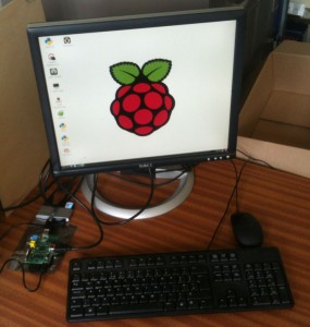
My first Raspberry Pi…

Raspberry Pi Type A with WiPi

Raspberry Pi Type A with WiPi

The setup:

  • Raspberry Pi Type A (one USB slot, no ethernet) that came with an 8GB SD card with Raspbian; supplied by RS Online (785-8645).
  • A Dell LCD, keyboard and mouse salvaged from a workstation purchased in… 2005, I think; has DVI and VGA inputs.
  • 1 powered USB hub: Belkin F5U415UK, 4 USB 2.0 ports; supplied by RS Online (480-217).
  • 1 power supply for the Raspberry Pi; supplied by Farnell (2254792).
  • 1 USB WiFi (WiPi) dongle; supplied by Farnell (2133900).
  • 1 HDMI-to-DVI lead: Pro Signal PSG02574; supplied by Farnell (1813133).

The Type A has no ethernet port, so I needed to get the WiFi working. The WiFi configuration tool was able to pick up the Newcastle University WiFi network, but was unable to maintain a connection.

Update (15/3/21)

I have received some official advice from the university about how to connect to the university without plain-text passwords.

Connecting Raspberry Pi to Enterprise Wi-Fi

(newcastle-university/eduroam)

Connecting to enterprise standard WiFi on a raspberry pi requires some additional setup in order to be able to connect.

  1. Whoever will be using/is responsible for it, will need to generate a password hash, otherwise they would be storing and transmitting their password in plain text over Wi-Fi. They can do this with:
    echo -n USERS_PASSWORD | iconv -t utf16le | openssl md4
  2. They then need to update the wpa_supplicant.conf file with the details below. To open the file, run:
    sudo nano /etc/wpa_supplicant/wpa_supplicant.conf
  3. Update that file to match the following details:
    network={
    	ssid="newcastle-university"
    	scan_ssid=1
    	key_mgmt=WPA-EAP
    	group=CCMP TKIP
    	eap=PEAP
    	identity="USERS_NID"
    	password=hash:USERS_PASSWORD_HASH
    	phase1="peapver=0"
    	phase2="MSCHAPV2"
    }
  4. Press Ctrl + O followed by Enter to save, then Ctrl + X to close the file
  5. Run the following command to apply and save the config:
    wpa_cli –i wlan0 reconfigure
  6. Wait for the Pi to show as connected to the WiFi network. At this point, you may need to restart for the connection to work.

Original Post – Non-Secure, Non-Recommended Method

(I think it can work if you do it right. The second Raspberry Pi that I set up picked up the settings automatically but I made the mistake of selecting MSCHAPV2 from the drop-down menu instead of PEAP, which resulted in the configuration line in the file below becoming “eap=MSCHAPV2” rather than “eap=PEAP”.)

I edited /etc/wpa_supplicant/wpa_supplicant.conf by hand afterwards to:

ctrl_interface=DIR=/var/run/wpa_supplicant GROUP=netdev
update_config=1

network={
	ssid="newcastle-university"
	proto=RSN
	key_mgmt=WPA-EAP
	pairwise=CCMP
	auth_alg=OPEN
	eap=PEAP
	phase2="auth=MSCHAPV2"
	identity="username"
	password="password"
}

You’ll need to use your username and password (plain text, unfortunately) there.

On reboot, the Raspberry Pi connected automatically to the university’s network and even the web proxy was detected and configured automatically.